
Anti-Jamming UAV Mesh Networking: Avionics & RF Guide
Star United Flight Control (Shaanxi) Technology Co., Ltd.
12 min read·2026-10-20
| Evaluation Dimension | Industrial Benchmark | Operational Testing Boundary | Procurement Red-Flags (What to Avoid) |
|---|---|---|---|
| RF Anti-Jam Processing | FHSS (>1,000 hops/s) + DSSS (>12 dB gain) | J/S ratio ≥ 35 dB @ 10 km baseline | Fixed-frequency COFDM with no frequency agility |
| MANET Re-Route Latency | Dynamic re-convergence < 800 ms | 50% simultaneous node attrition across 6 nodes | Static IP-bridged mesh stalling telemetry > 3.0 s |
| Avionics Bus Isolation | Triple CAN 2.0B per ISO 11898-2 + opto-isolation | RTCA DO-160G Section 21 (RF Susceptibility Cat R) | Shared single UART/I2C buses without galvanic isolation |
| Environmental & Thermal | Conduction-cooled enclosure, IP67 per IEC 60529 | Continuous transmission at +45°C ambient, 100% duty cycle | Internal SDR junction > 85°C resulting in RF power drop |
| SWaP-C Payload Derating | Radio subsystem ≤ 18% total mission payload weight | Full continuous power draw ≤ 35 W DC at nominal bus | RF payload draws > 30% battery reserve, cutting flight time by > 40% |
Operational Rubric: Evaluating Anti-Jam Mesh Systems for Industrial UAS
Mesh networking for anti-jamming UAV operations deploys decentralized, peer-to-peer ad-hoc topologies where every node routes telemetry and payload data autonomously without reliance on a centralized base station. By coupling rapid frequency-hopping spread spectrum waveforms with deterministic link-state routing, these systems maintain non-line-of-sight (NLOS) command-and-control (C2) under deliberate broad-spectrum electronic attack and localized radio-frequency (RF) denial. In congested industrial frequency bands (902–928 MHz, 1.4 GHz, 2.4 GHz, and 5.8 GHz), industrial unmanned aerial systems face severe physical constraints. Traditional point-to-point links create single points of failure: when an electronic warfare (EW) asset or high-power industrial emitter degrades the ground-to-air link, the unmanned vehicle triggers emergency fail-safes or loses operational control. Decentralized Mobile Ad-Hoc Networks (MANET) resolve this vulnerability by dynamically distributing data streams across multiple airborne nodes, allowing signals to bypass localized jamming cones through alternate spatial vectors.Mobile Ad-Hoc Network (MANET): A self-configuring, infrastructure-less network of mobile devices connected wirelessly. Each node in a MANET participates in routing by forwarding data dynamically to other nodes based on real-time link quality metrics.Deploying anti-jam MANET topologies imposes strict trade-offs across weight, electrical power, thermal envelope, and RF processing margins. Enterprise procurement evaluations must analyze these trade-offs using rigorous engineering frameworks rather than vendor assertions.
Physical Layer RF Resilience: Modulation, Dwell Times, and Throughput Trade-offs
At the physical (PHY) layer, surviving high Jammer-to-Signal (J/S) environments requires combining Frequency Hopping Spread Spectrum (FHSS), Direct Sequence Spread Spectrum (DSSS), and adaptive Coded Orthogonal Frequency Division Multiplexing (COFDM). The processing gain (Gp) dictates the system's ability to extract packet symbols from broadband noise floor elevations.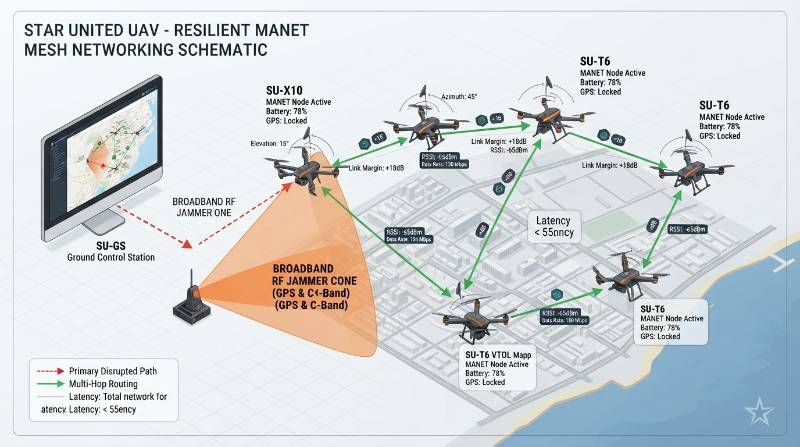
Hop Rate Dynamics and Dwell Time Physics
FHSS resilience depends directly on the relationship between hop dwell time (Td) and the adversary's intercept-and-follow loop time. If an SDR platform hops across a 40 MHz allocation with a dwell time of 800 μs (>1,200 hops/sec), reactive sweep jammers cannot sample the energy, lock phase loops, and broadcast spot interference before the node transitions to the next pseudo-random channel.- Fast Hopping (>1,000 hops/s): Symbol duration is shorter than or equal to hop dwell time. Mitigates sweep and reactive jamming, but introduces packet header overhead (15% to 22% effective throughput penalty).
- Slow Hopping (<200 hops/s): Multiple symbols transmit per hop. Maximizes video payload bandwidth, but remains vulnerable to fast sweep jamming systems.
- DSSS Processing Gain: Formulated as Gp = 10 × log10(BRF / Rb), where BRF is RF bandwidth and Rb is the baseband data rate. A 20 MHz spread over a 100 kbps telemetry stream yields a 23 dB processing gain, allowing telemetry lock at negative signal-to-noise ratios (-8 dB SNR).
Adaptive Modulation Thresholds
Dynamic link management algorithms continuously adjust modulation schemes based on instantaneous Packet Error Rate (PER) and link margin metrics. When approaching high-power industrial emitters or active electronic countermeasures, platforms drop throughput to protect core MAVLink 2.0 flight packets: High-order modulations like 64-QAM require an SNR exceeding 22 dB to maintain a PER below 10-3, delivering up to 28 Mbps for dual-stream high-definition video. Under contested conditions, the physical layer steps down to QPSK (SNR threshold ≈ 10 dB, yielding 4 to 8 Mbps) and ultimately to robust BPSK (SNR threshold ≈ 4 dB, sustaining 1.2 Mbps). In worst-case conditions with J/S > 30 dB, the system drops video streaming entirely, utilizing DSSS-modulated BPSK to preserve the 50 kbps command-and-control link connected to triple-redundant flight control systems.Airborne MANET Routing: Latency Modeling and Multi-Hop Topology Degradation
Airborne network nodes navigate three-dimensional vector space at velocities ranging from 0 m/s (hover) to 35 m/s (dash), causing rapid RF path loss variations and dynamic link geometry changes. The selection of ad-hoc routing protocol determines multi-hop packet convergence and end-to-end telemetry stability.
Proactive vs. Reactive Routing Mechanics
The routing protocol must manage high node mobility while minimizing the bandwidth consumed by routing control packets. Standards defined under IETF RFCs govern these behaviors across decentralized aerial nodes.- Optimized Link State Routing (OLSR / RFC 3626): A proactive protocol that maintains network topology state via continuous link evaluations and Multipoint Relays (MPRs). Convergence following node destruction occurs in <600 ms. However, steady-state routing overhead consumes 12% to 18% of available channel capacity, making it resource-intensive for high-node-count swarms.
- Ad-Hoc On-Demand Distance Vector (AODV / RFC 3561): A reactive protocol that establishes routes only upon packet transmission requests via Route Request (RREQ) and Route Reply (RREP) exchanges. While consuming negligible idle bandwidth (<2%), discovery delays under abrupt link disruption introduce latency spikes of 1,200 to 2,400 ms, exceeding standard MAVLink heartbeat timeout limits (typically 1,000 ms).
- Hybrid Airborne Protocols (B.A.T.M.A.N. Advanced / HWMP per IEEE 802.11s): Operates at Layer 2 (Data Link) rather than Layer 3. Frame encapsulation at Layer 2 eliminates IP routing delays, maintaining multi-hop latency below 28 ms per hop across up to 4 aerial relay tiers.
Multi-Hop Latency and Packet Delivery Ratio (PDR)
End-to-end latency accumulates non-linearly over multiple wireless hops. In a 3-hop relay chain across an operational radius of 18 km, total round-trip latency consists of serialization delay (≈1.2 ms), media access contention delay (≈8–15 ms per hop using CSMA/CA), physical propagation delay (3.3 μs/km), and frame validation processing (≈4 ms). Real-world field measurements indicate that beyond 4 hops, aggregate latency exceeds 150 ms, inducing measurable control loop phase lag during manual remote piloting operations.Avionics Integration & SWaP-C Derating: Thermal Budgets in IP67 Enclosures
Integrating high-power Software-Defined Radios (SDR) into unmanned platforms introduces significant Size, Weight, Power, and Cooling (SWaP-C) constraints. Operating 2W to 10W RF output transceivers requires evaluating raw electrical draw against airframe thermal dissipation limits.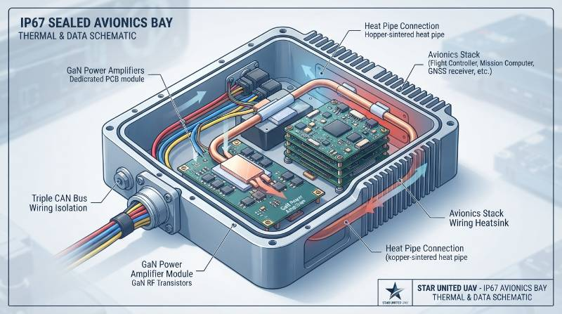
Conduction Cooling in Sealed Enclosures
Per IEC 60529 IP67 specifications, mission avionics bays must prevent particulate ingress and withstand water immersion at a 1-meter depth for 30 minutes. This excludes the use of forced-air ventilation or chassis perforations. Gallium Nitride (GaN) Power Amplifiers (PA) typically operate at electrical-to-RF power efficiencies of 32% to 40%. A dual-band MIMO transceiver delivering 10W total RF output draws 28W to 35W DC continuously. Without convection cooling, thermal flux must transfer entirely via solid-state conduction through 6061-T6 aluminum mounting plates to the external airframe skin. Thermal interface pads must exhibit a thermal conductivity exceeding 6.0 W/m·K. If junction temperatures exceed 85°C, SDR firmware initiates protective thermal throttling, cutting RF power output by 3 dB to 6 dB (reducing output power by 50% to 75%) and dropping the operational link margin below acceptable thresholds.Payload Mass vs. Flight Reserve Trade-offs
Deploying heavy SDR enclosures, antenna arrays, and dedicated thermal heatsinks reduces usable flight time. The operational endurance curve of a standard 12S lithium-power platform illustrates this physical trade-off:
- Unladen Platform (0.0 kg Payload): Hover endurance: 52 minutes; total pack draw: 32 A at 44.4 V nominal.
- Standard Telemetry Payload (1.5 kg - Low SWaP SDR): Hover endurance: 44 minutes; link range: 8 km line-of-sight.
- Hardened High-Power MANET Stack (4.5 kg - High-gain RF PA + heatsink + antennas): Hover endurance drops to 34 minutes (a 34.6% reduction from baseline). Total electrical draw increases to 48 A.
- Maximum Rated Mission Load (12.5 kg Dual Sensor + Relay Stack): Hover endurance drops to 28 minutes. In this configuration, the propulsion system operates closer to its thermal margin, requiring conservative flight profiles under high ambient temperatures.
The 4-Dimensional Contested-Spectrum Evaluation Matrix (CSEM-4)
To establish standardized verification criteria for industrial UAV procurement, enterprise engineering teams utilize the Contested-Spectrum Evaluation Matrix (CSEM-4). This framework scores platforms across four operational domains to determine mission viability under electronic interference.| Matrix Dimension | Evaluation Metric | Target Performance Standard | Applicable Industry Standard |
|---|---|---|---|
| 1. Dynamic Link Survivability | Jammer-to-Signal (J/S) tolerance; hop rate; processing gain | ≥ 35 dB J/S rejection; >1,000 hops/s; PER < 2% | MIL-STD-461G / RTCA DO-160G Sec 21 |
| 2. Deterministic Convergence | Dynamic re-routing time; multi-hop jitter | Network recovery < 800 ms; jitter < 120 ms over 3 hops | IEEE 802.11s / RFC 3626 (OLSR) |
| 3. SWaP Platform Reserve | Avionics draw ratio; thermal dissipation path | Radio draw < 18% MTOW capacity; SDR Tj < 65°C @ 45°C amb | MIL-STD-810H Method 501.7 |
| 4. Bus Isolation & Nav Failover | Internal EMI isolation; GNSS-denied dead reckoning | Triple CAN bus; VIO drift < 0.15% distance traveled | ISO 11898-2 / RTCA DO-160G Sec 20 |
Empirical Benchmark: Heavy-Lift Multirotor Relay in Marine and High-EMF Corridors
Field verification demonstrates the operational efficacy of mesh protocols under extreme electro-magnetic and environmental stress. In benchmark evaluations conducted per ISO 21384-3 standards on Star United heavy-lift rotary UAV platforms, systems were tested across high-voltage utility infrastructure and offshore corridors.Test Parameters and Environmental Profile
- Location Profile: Coastal 500 kV Ultra-High Voltage (UHV) transmission substation switching yard.
- Atmospheric Conditions: Sustained marine winds of 14 m/s, gusts to 17.5 m/s (Beaufort 7), ambient temperature 38°C, relative humidity 82% with high marine salinity.
- EMF Exposure: Radiated field strengths exceeding 100 V/m adjacent to phase transformers, inducing broadband harmonic interference.
- Payload Configuration: 12.5 kg payload comprising a dual gimbal-stabilized MWIR/EO sensor and a 1.4 GHz / 2.4 GHz dual-band high-power MANET relay node.
Telemetry Findings and Navigation Failover
During proximity transit within 12 meters of 500 kV transformer bushings, standard GNSS receivers (L1/L2 multi-constellation) suffered total carrier-to-noise density (C/N0) degradation below 25 dB-Hz, inducing complete GNSS positioning loss. The platform executed autonomous station-keeping via drift-constrained Visual-Inertial Odometry (VIO) coupled with downward-facing pulsed LiDAR altimetry, maintaining hover position within ±0.08 m horizontal drift over 10 minutes of complete satellite lock denial. Concurrently, intentional localized RF interference was introduced across the 2.4 GHz control band. The onboard MANET node executed seamless channel hops to unoccupied 1.4 GHz bands within 42 ms. Using dual galvanically isolated CAN 2.0B buses per ISO 11898-2, the airframe isolated high-power RF PA transients from flight control telemetry, preventing autopilot reboot cycles or register corruptions during prolonged critical industrial infrastructure inspection maneuvers.Platform Architecture Trade-offs: Hybrid VTOL vs. Heavy-Lift Multirotor in EW Scenarios
Selecting an airframe for anti-jam mesh relay deployments requires balancing spatial aerodynamics against RF link physics. Both multi-rotor and hybrid vertical take-off and landing configurations introduce distinct architectural trade-offs.Hover Stability and Spatial Diversity
Heavy-lift multirotors provide precise zero-groundspeed hovering capability. This allows directional high-gain antennas to remain continuously aligned with remote ground stations or maritime vessels regardless of wind drift. Furthermore, structural motor arm spacing exceeding 1,400 mm facilitates wide physical separation of MIMO antenna pairs, maximizing spatial de-correlation and improving multi-path rejection in cluttered industrial sites. Conversely, hybrid VTOL fixed-wing UAVs require continuous forward airspeed (typically 22 to 28 m/s) during cruise flight. Loitering in fixed orbits induces dynamic antenna pattern nulls relative to the ground control station as the airframe banks, requiring omni-directional low-gain antennas or complex mechanical tracking gimbals that introduce additional mass and mechanical failure points.MTOW Allocation and Mission Critical Reserves
Multirotors allocate between 40% and 52% of Maximum Take-Off Weight (MTOW) to usable batteries and payloads, tolerating heavy GaN amplifiers and robust passive heatsinks. When unexpected subsystem anomalies occur under heavy jamming, a multirotor executes an immediate controlled descent or parachute deployment per ASTM F3322-18 standards. Hybrid VTOL platforms, constrained by wing loading limits and center-of-gravity envelopes, allocate only 20% to 30% of MTOW to operational avionics payloads, leaving narrower margins for heavy RF hardware and passive cooling infrastructure.Technical Verification & Procurement FAQ
What are the structural trade-offs between Hybrid VTOL and Heavy-Lift Multirotors in contested-spectrum mesh operations?
Heavy-lift multi-rotors provide zero-groundspeed station-keeping during link loss and antenna arm separation (>1,400 mm) optimal for MIMO de-correlation without nulls. They dedicate 40% to 50% of MTOW to usable payload and radio hardware, allowing immediate vertical landing upon critical system fault. Hybrid VTOLs offer greater forward transit efficiency and extended operational radius, but cannot maintain static RF link geometry, suffer from antenna spacing constraints within narrow composite fuselages, allocate only 20% to 30% of MTOW to operational payloads, and require clear, unobstructed glide paths for emergency landing aborts.How can enterprise procurement teams verify authentic IP67 sealing and anti-jamming mesh capabilities without relying on vendor datasheets?
Procurement audits should mandate three specific test procedures:- Differential Pressure Decay Testing: Enclosures must undergo differential pressure decay at ΔP = 10 kPa, confirming a leakage rate resulting in pressure drops <20 Pa over a 60-second dwell per IEC 60529 guidelines.
- Anechoic Chamber RF Stress Verification: Test radios against an active swept-chirp jammer emitting +30 dBm Equivalent Isotropically Radiated Power (EIRP) at a 5-meter range. Verify that frequency-hopping re-synchronization occurs within <50 ms and packet error rates on MAVLink 2.0 telemetry streams remain below 2.0%.
- Thermal Soak Bench Testing: Radios must operate at 100% duty cycle transmission for 45 continuous minutes in a +40°C thermal chamber. Monitor internal junction temperatures to verify they remain below 65°C without triggering amplifier thermal cutoffs or dropping RF output power below 8 Mbps.
What are the realistic lifecycle maintenance intervals and MTBF metrics for industrial anti-jam UAS?
Industrial platforms compliant with ASTM F3298-19 design parameters specify Mean Time Between Failures (MTBF) exceeding 1,500 flight hours for core flight avionics. Brushless propulsion systems require mandatory motor bearing replacements and dynamic rotor balancing at 500 flight hours. Modular quick-disconnect arm interfaces allow field Mean Time to Repair (MTTR) under 25 minutes using standard metric hand tools, minimizing depot-level maintenance cycles.Avionics Integration & Flight Feasibility Pathway
Enterprise drone deployments requiring hardened mesh topologies in contested or high-EMF spectrum environments follow a structured 3-step engineering onboarding sequence:- Step 1: Mission Profile & Spectrum Parameter Intake: Define operational frequencies, expected jammer power density, RF exposure levels, payload mass, and continuous flight duration requirements.
- Step 2: Automated Avionics & SWaP-C Feasibility Report: Systems engineers execute link margin budgeting, center-of-gravity calculations, and thermal modeling to determine power-to-weight margins and payload endurance degradation curves.
- Step 3: Direct Consultation with Senior Flight Integration Engineers: Review full CAD STEP files, hardware-in-the-loop (HIL) simulation telemetry, and certified test reports compliant with RTCA DO-160G and IEC 60529 standards.
Request Avionics Integration & Feasibility Support
Access engineering CAD STEP airframe files, subsystem electrical draw models, and direct consultation for your payload architecture with Star United UAV integration specialists.
Consult a Systems Integration Specialist