
GPS-Denied UAV Ground Control Station Architecture Guide
Star United Flight Control (Shaanxi) Technology Co., Ltd.
11 min read·2026-10-25
Architectural Demands of Non-GNSS Ground Control Stations
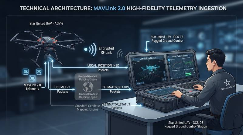
Deploying unmanned aircraft systems within satellite-deprived operational theaters requires ground stations to decouple from absolute global positioning frameworks entirely. A compliant industrial ground control system must ingest, parse, and arbitrate high-rate relative state estimation streams while managing dynamic RF link margins in hostile environments. When GPS constellations fail due to physical obstruction, multipath degradation, or active RF jamming, the software interface cannot rely on conventional geodetic mapping layers.GPS-Denied GCS Operation: The deterministic execution of supervisory command and control (C2), telemetry parsing, and spatial awareness using local Cartesian frames (NED) and relative payload odometry without dependency on the global World Geodetic System 1984 (WGS-84) datum.Commercial GCS architectures running generic software layers trigger critical operational hazards in these theaters. When an autopilot's navigation filter encounters satellite loss, standard interfaces lock their geographical canvas, trigger invalid Return-to-Launch (RTL) routines, or crash due to floating-point exceptions in coordinate transformations. Systems must parse relative sensor streams at ≥ 50 Hz, visualize error states deterministically, and preserve low-latency operator override pathways per ISO 21384-3 operational baselines.
GCS Architectural Specifications & Industrial Benchmark Matrix
In benchmark field evaluations conducted per ISO 21384-3 and ASTM F3322-18 on heavy-lift rotary platforms, ground stations revealed stark demarcations between standard commercial designs and mission-critical hardware. The following engineering matrix identifies performance boundaries, standard validation methods, and architectural non-compliances.| Evaluation Dimension | Industrial Benchmark | Operational Testing Boundary | Selection Red-Flags (What to Avoid) |
|---|---|---|---|
| Coordinate Ingestion Engine | Dynamic WGS-84 to Local Tangent Plane (NED) decoupling at ≥ 50 Hz. | Maintains relative tracking across sudden HDOP jumps from 0.8 to > 50.0. | Software freezes, canvas lockups, or hardcoded dependencies on GLOBAL_POSITION_INT. |
| Display Latency & Sensor Fusion | Sub-map rendering (LiDAR/VIO) with covariance ellipses at ≤ 45 ms glass-to-glass. | Point cloud density of 100,000 pts/sec rendered over local 2.4/5.8 GHz wireless link. | Telemetric frame lag > 150 ms; failure to render spatial drift bounds. |
| RF Immunity & Modulation | COFDM with adaptive FHSS; > 18 dB link margin in high multipath clutter. | Operates adjacent to 100 V/m field emissions per RTCA DO-160G Section 20/21. | Unshielded standard Wi-Fi/Bluetooth COTS protocols; single-frequency transceivers. |
| Hardware Ingress & Ruggedization | Milled aluminum chassis; IEC 60529 IP67 rating; internal ePTFE pressure venting. | 30 min submersion at 1 m depth; thermal cycling across -20°C to +55°C. | Consumer plastic housings, exposed passive cooling vents, non-sealed I/O ports. |
| Safety & Termination Interop | Independent hardware-level flight termination system per ASTM F3322-18. | Dedicated secondary link activation (e.g., 433/868 MHz) within < 15 ms command delay. | Software-only kill switches routing through primary frozen telemetry packets. |
The GCS-NDR 4-Dimensional Reliability Framework
To establish baseline operational standards for contested operations, our engineering team defines the GCS-NDR (Non-GNSS Deterministic Reliability) Framework. This methodology governs avionics telemetry integration, RF propagation margins, visual telemetry translation, and system survivability.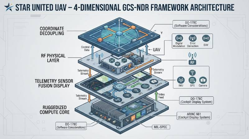
1. Coordinate Frame Dynamic Decoupling
The GCS must dynamically transition between geodetic (WGS-84) frames and metric Local Tangent Planes (NED or ENU) without operator manual intervention. Autopilots broadcastLOCAL_POSITION_NED (MAVLink #32) and high-precision metric matrices via ODOMETRY (MAVLink #331). When GNSS fix degrades (Horizontal Dilution of Precision, HDOP > 4.0), the GCS display layer must unpin from world map tiles, establishing the origin (0,0,0) at the arming point, SLAM origin, or a designated Ultra-Wideband (UWB) beacon node.
2. RF Physical-Layer Immunity & Dynamic Link Budgeting
High-EMF industrial clutter and active RF jamming degrade generic wireless streams. GCS field hardware requires Coded Orthogonal Frequency Division Multiplexing (COFDM) combined with fast Frequency-Hopping Spread Spectrum (FHSS) across split industrial bands (such as 800 MHz and 1.4 GHz). Ground terminals must sustain an 18 dB fade margin to prevent telemetry loss caused by structural multipath reflections within metal-dense industrial environments.3. Real-Time Edge Telemetry Processing & Sensor Fusion Display
State estimation during satellite blackouts depends on onboard LiDAR Odometry and Visual-Inertial Odometry (VIO). The ground station must ingest, parse, and render onboard spatial tracking pipelines at frame rates exceeding 30 fps. The GCS visual layer must dynamically draw spatial covariance ellipses representing the Extended Kalman Filter (EKF3) uncertainty boundaries, providing operators with actionable spatial drift limits in real time.4. Hardware-Level Physical Ruggedization & Computational Autonomy
GPS-denied zones frequently correlate with severe environmental hazards: marine salt spray, desert thermal loading, or subterranean moisture. Ground hardware must possess IEC 60529 IP67 sealed enclosures, active internal heat-pipe thermal distribution, and complete offline autonomy. Cloud-dependent authentications, offsite map servers, or non-deterministic operating systems introduce fatal points of failure in field operations.Telemetry Ingestion, State Estimation, and Covariance Mapping
Deterministic command of high-reliability platforms requires deterministic telemetry integration inside the vehicle's flight control systems. Standard MAVLink implementations rely onGLOBAL_POSITION_INT (Message #33), which aggregates fused GNSS data to broadcast latitude, longitude, and ellipsoidal altitude. When satellite tracking fails, this message's validity bit transitions to zero, causing conventional ground stations to flag vehicle telemetry as invalid.
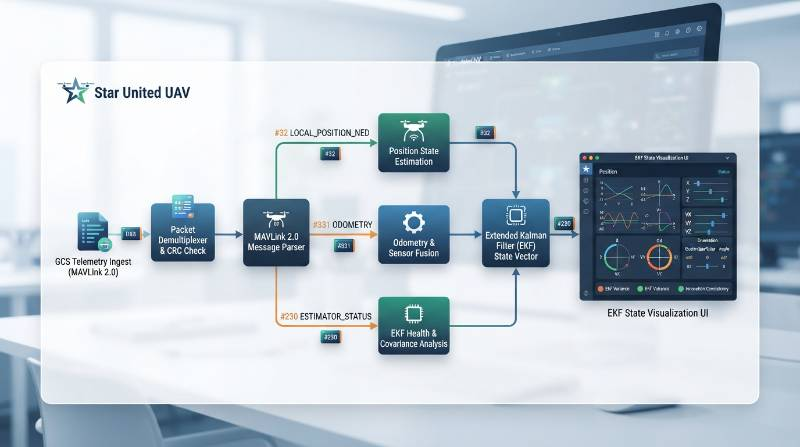
LOCAL_POSITION_NED(Message #32): Ingests metric position (x, y, z) and velocity vectors (vx, vy, vz) relative to a local origin at ≥ 50 Hz.ODOMETRY(Message #331): Ingests full 6-DoF pose and twist along with upper-triangular covariance matrices from onboard Visual-Inertial Odometry (VIO) or LiDAR SLAM systems.ESTIMATOR_STATUS(Message #230): Ingests specific sub-filter ratios tracking velocity variance, horizontal position variance, vertical position variance, and compass consistency.
ESTIMATOR_STATUS horizontal position variance metric exceeds 0.8, the ground station UI must visually expand the vehicle's spatial position tolerance ring. This mechanism warns operators that while the relative state estimation remains functional, spatial drift accumulation mandates route adjustments or controlled landing sequences before covariance divergence triggers physical collision.
Relative Coordinate Mission Planning & Dynamic Geofencing
Mission planning across satellite-denied structures cannot reference fixed latitude and longitude coordinates. Operators conducting industrial inspection within high-voltage substations, confined indoor tunnels, or offshore turbine nacelles require Cartesian waypoint scripting anchored to local physical geometry.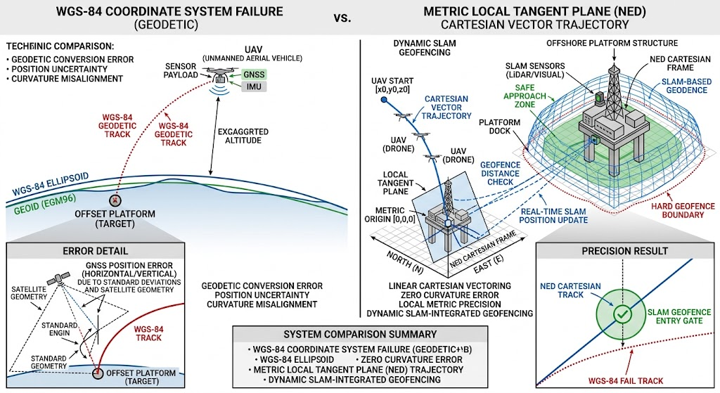
dorigin = (ΔX2 + ΔY2 + ΔZ2)1/2
If dorigin exceeds the defined mission envelope boundary, or if the estimated covariance drift ellipse overlaps an obstacle boundary within the LiDAR point cloud by less than 1.5 meters, the GCS automatically transmits an immediate deterministic holding instruction (e.g.,MAV_CMD_DO_PAUSE_CONTINUE) over low-latency telemetry pipelines.
RF Link Budgeting and Communications in High-EMF Clutter
Wireless propagation in industrial environments is heavily impeded by multipath cancellation, phase distortion, and electromagnetic interference (EMI). A ground control station managing non-GNSS operations must maintain continuous RF margins to preserve real-time control, as loss-of-signal fail-safe procedures (such as satellite-guided automated return) are physically unavailable.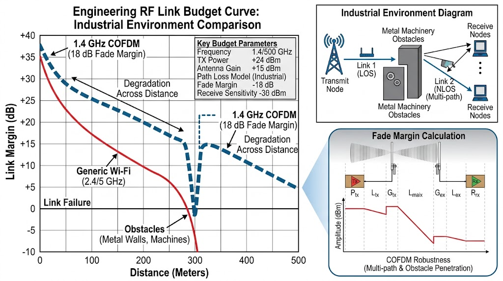
PRX = PTX + GTX + GRX - LFS - Lclutter - Lfade
Where PTX represents transmitter output power, G represents antenna gains, LFS is free-space path loss, Lclutter quantifies absorption and reflection attenuation, and Lfade defines required multipath fade margin. In standard configurations delivering 30 dBm (1.0 W) output across a 1.4 GHz link with 3 dBi transmitter and 8 dBi ground receiver patch antennas, free-space loss at 1.5 km equals approximately 99 dB. In high-interference environments, metallic infrastructure introduces 15 dB to 25 dB of additional clutter loss. Under these conditions, generic commercial ground stations experience complete telemetry packet drop. To assure deterministic telemetry delivery, industrial GCS hardware must incorporate receiver sensitivities down to -102 dBm at 2 MHz channel bandwidth using COFDM modulation (QPSK 1/2 rate). This configuration retains an operational fade margin exceeding 18 dB. Furthermore, RF hardware must be shielded and tested per RTCA DO-160G Section 20/21 (Category R) to guarantee operational immunity against radiated fields up to 100 V/m.Operational Boundaries, Derating Curves, and Subsystem Lifecycle
Operating a tactical or industrial aerial platform requires clear visibility into physical operational boundaries. Heavy payload multi-rotor aircraft, such as a specialized industrial heavy-lift rotary UAV, present steep payload-versus-endurance derating curves that must be computed and accounted for within the GCS battery telemetry pipeline.Payload-Versus-Endurance Derating Curves
Hover flight endurance scales inversely with all-up weight. On an 8-rotor heavy-lift propulsion architecture operating a 48V (12S) solid-state battery system (40 Ah capacity):- Empty Configuration (0 kg payload, 18.5 kg AUW): Hover endurance achieves 58 minutes under zero-wind sea-level conditions.
- Nominal Operational Payload (5.0 kg payload, 23.5 kg AUW): Hover endurance derates to 41 minutes (derating coefficient ≈ 3.4 min/kg).
- Maximum Rated Payload (10.0 kg payload, 28.5 kg AUW): Hover endurance drops to 24 minutes. Current draw increases from 38 A to 92 A, elevating motor winding temperatures significantly.
Environmental & Thermal Boundaries
Both vehicle propulsion batteries and internal GCS power modules experience severe capacity derating under thermal extremes. At -20°C, lithium-ion electrolyte viscosity increases, elevating internal impedance (ESR) and reducing usable discharge capacity by up to 38% unless autonomous internal battery pre-heating is engaged. At temperatures exceeding +50°C, continuous discharge induces electronic speed controller (ESC) and motor thermal throttling, requiring the GCS to enforce a 20% safety margin on all automated climb trajectories.Wind & Gust Thresholds
Aerodynamic control authority must be strictly distinguished between continuous operation and survivability limits per IEC 60068-2-6:- Maximum Continuous Operational Wind: 12 m/s (23.3 knots). Flight trajectory tracking divergence remains below ± 0.15 m.
- Maximum Survivable Gust Limit: 15 m/s (29.1 knots). The flight controller commands maximum counter-torque attitude excursions up to 38°, preserving structural holding while relative station-keeping error expands up to ± 1.2 m.
Total Cost of Ownership, MTBF, and Overhaul Cycles
Reliability requires strict lifecycle tracking logged directly through the GCS maintenance analytics engine. Enterprise procurement models must incorporate these empirical intervals:- System Mean Time Between Failures (MTBF): Exceeds 1,500 continuous operational flight hours for primary flight avionics.
- Motor Bearing Overhaul: Mandatory replacement interval at 500 operating hours to prevent bearing seizure caused by dynamic dust intrusion.
- GCS Mechanical Controls: Industrial Hall-effect gimbals recalibrated at 600-hour intervals; potentiometers replaced to eliminate physical center drift.
- Mean Time to Repair (MTTR): Standard field module replacement (such as quick-disconnect arm assemblies or RF transceiver cards) engineered at < 25 minutes using standard hex tooling.
Technical Verification & Engineering Architecture FAQ
Why do standard GCS platforms fail when operating UAVs in GPS-denied environments?
Standard GCS platforms depend strictly on the WGS-84 coordinate frame populated via MAVLink #33GLOBAL_POSITION_INT. When satellite signals fail or are spoofed, standard GCS map layers freeze, geofencing breaks, and automated RTL commands execute errantly toward invalid coordinate origins. Ruggedized non-GNSS GCS platforms resolve this by deploying an autonomous Local Frame Translation Engine: they decouple from satellite coordinates and parse MAVLink #32 LOCAL_POSITION_NED and #331 ODOMETRY streams. The interface switches to a metric-relative Euclidean workspace anchored to the GCS location, SLAM origin, or an optical target, preserving real-time C2 and spatial awareness without GNSS.
How can technical procurement auditors verify supplier claims regarding IP67 ingress protection?
Technical auditors must verify three structural factors: First, external interfaces must use industrial or military circular push-pull connectors (such as Amphenol or LEMO rated to IP68) rather than consumer rubber covers over commercial USB or HDMI ports. Second, enclosures must integrate an expanded polytetrafluoroethylene (ePTFE) hydrophobic membrane vent to equilibrate internal pressure differentials during thermal cycling (-20°C to +55°C) without drawing moisture past perimeter gaskets. Third, demand manufacturer laboratory test records confirming compliance with IEC 60529 Clause 14.2.7 (continuous water immersion at 1.0 meter depth for 30 minutes) and RTCA DO-160G Section 8 vibration endurance.What causes telemetry bandwidth contention during high-definition point cloud streaming?
Streaming uncompressed dense LiDAR point clouds requires data bandwidths exceeding 25 Mbps. In contested or cluttered RF environments where modulation automatically downshifts to robust BPSK or QPSK modes, total channel capacity often restricts to 4 to 8 Mbps. If telemetry and sensor streams share an unmanaged physical link, point cloud packets contend with critical MAVLink flight commands, causing command latency to spike above 500 ms. Industrial systems resolve this by processing sensor fusion data on an embedded edge computer (such as an NVIDIA Jetson Orin) on the aircraft, transmitting only downsampled octree occupancy grids and trajectory covariance matrices to the GCS at data rates below 1.5 Mbps.How does the GCS identify and respond to intentional GNSS spoofing?
GNSS spoofing typically presents as an anomalous divergence between satellite-reported pseudorange rates and inertial accelerometer integrations. The onboard triple-redundant IMU Extended Kalman Filter flags an innovation variance spike in horizontal velocity. The GCS monitors MAVLink #230ESTIMATOR_STATUS flags. When the innovation variance exceeds 1.0, the GCS immediately alerts the operator and initiates a deterministic command handshake: it commands the autopilot to sever GNSS weights from the EKF, transitions primary state estimation to optical flow, VIO, or LiDAR odometry, and switches the operator visualization display to relative metric mode.
Procurement Validation: 3-Stage Technical Integration Pathway
Integrating mission-critical UAV systems into satellite-compromised operations demands a structured engineering integration methodology. Enterprise operators must execute validation across three stages:- Stage 1: Payload & Environmental Audit The technical team submits full operational profiles: RF clutter spectrum measurements, extreme operating temperature envelopes (-20°C to +55°C), maximum wind gust baselines, required sensor payloads (LiDAR, optical, radiometric thermal), and MAVLink schema requirements.
- Stage 2: GCS Telemetry & RF Architectural Blueprint Avionics engineers evaluate the physical-layer RF link budget, define COFDM channelization plans, and configure MAVLink message translation pipelines for non-WGS-84 metric display, delivering a system-level mechanical and electrical interface schematic.
- Stage 3: Hardware-in-the-Loop Demonstration & Field Deployment Systems undergo comprehensive Hardware-in-the-Loop (HIL) bench simulation to verify fault handling under simulated GNSS jamming, multipath interference, and sudden telemetry degradation. Field flight test delivery confirms full compliance per ASTM F3298 and ISO 21384-3 standards.
Request Technical CAD STEP Blueprints & Engineering Consultation
Access detailed payload power consumption budgets, physical interface dimensions, and direct consultation with senior avionics integration engineers.
Consult UAV Integration Engineers