
EO/IR vs SAR Radar for UAV Surveillance: Engineering Guide
Star United Flight Control (Shaanxi) Technology Co., Ltd.
11 min read·2026-10-22
| Evaluation Dimension | Industrial Benchmark | Operational Testing Boundary | Selection Red-Flags (What to Avoid) |
|---|---|---|---|
| Atmospheric Penetration | X/Ku-band SAR: <0.1 dB/km loss in heavy fog; MWIR/EO: >35 dB/km loss per Beer-Lambert. | Precipitation rates up to 25 mm/hr per ITU-R P.838; relative humidity >95% at 10°C. | Deploying standalone optical payloads for maritime advection fog without active RF cross-cueing. |
| SWaP-C Electrical Load | Mini-SAR: 120–220 W steady-state; Cooled MWIR: 40–75 W; Uncooled LWIR: 12–25 W. | Continuous draw across -20°C to +50°C thermal envelope per RTCA DO-160G Section 4. | Omitting battery internal resistance derating at -20°C, inducing unexpected ESC low-voltage cutoff. |
| Airframe Trajectory & Stability | SAR: <0.02° trajectory phase error; EO/IR: 3-axis stabilization jitter <15 μrad. | Beaufort Scale 8 wind (17.2–20.7 m/s) with high-frequency structural vibration >120 Hz. | Single-antenna GNSS architectures unable to provide real-time dual-antenna heading during zero-airspeed hover. |
| Target Exploitation & DRI | EO/IR: STANAG 4347 positive optical identification; SAR: Polarimetric surface roughness & GMTI. | MISB ST 0601 metadata compliance at 1080p60 vs raw phase backprojection <1.5 s latency. | Relying on SAR phase backprojection for facial or tail-number optical identification verification. |
| Environmental & Mechanical Integrity | Hermetic enclosure sealing certified to IEC 60529 IP67; salt-spray resistance to MIL-STD-810H. | 30-minute submersion at 1.0 m; 48-hour continuous 5% NaCl marine aerosol exposure. | Unsealed plastic or vent-cooled avionics enclosures deployed in corrosive coastal marine environments. |
Technical Specifications & Industrial Surveillance Evaluation Matrix
Airborne surveillance payloads for industrial and defense operations diverge fundamentally in physical sensing modalities, with Electro-Optical/Infrared (EO/IR) turrets delivering sub-10 μrad spatial resolution for positive optical identification, and Synthetic Aperture Radar (SAR) providing cloud-penetrating active microwave backscatter mapping. While EO/IR operations collapse when atmospheric particulate extinction exceeds 30 dB/km, X-band and Ku-band mini-SAR systems maintain constant ground reflectivity mapping at the expense of an operational power draw 3× to 8× greater than comparable passive optics. Selecting between or fusing these payloads requires rigorous physical envelope modeling across atmospheric attenuation, platform integration dynamics, and host airframe power margins. Engineering procurement teams evaluating airborne ISR surveillance solutions must balance sensor resolution against mechanical and environmental limitations. Systems deployed without empirical verification against operational boundaries inevitably suffer payload brownouts, loss of phase coherence, or severe visual sensor starvation during degraded visual environments (DVE).The Empirical Airborne Surveillance Evaluation Matrix (E-PAM™)
To eliminate ambiguity in payload selection, the Empirical Airborne Surveillance Evaluation Matrix (E-PAM™) defines an objective, physics-based architecture rubric across four non-negotiable vectors: Spectral Physics, SWaP-C Budgets, Dynamic Coupling, and Data Pipeline Exploitation.E-PAM™ Framework Definition: A multi-tiered avionics qualification standard establishing mathematical verification gates for UAV payload integration based on measured atmospheric extinction coefficients, continuous bus power derating across RTCA DO-160G thermal envelopes, real-time trajectory motion-compensation latency, and low-latency digital pipeline backprojection.
The Four Architectural Pillars of E-PAM™
- Spectral & Atmospheric Physics: Analyzes photon transport through the atmosphere via the Beer-Lambert extinction law for optical/thermal sensors against microwave dielectric backscatter and volumetric rain attenuation calculated per ITU-R P.838.
- SWaP-C & Thermal Profile: Enforces continuous electrical load modeling comparing 120–220 W mini-SAR continuous RF generation against 12–60 W EO/IR gimbal stabilization across -20°C to +50°C operational boundaries per RTCA DO-160G Section 4.
- Airframe Aerodynamic Coupling: Defines acceptable motion-error boundaries, contrasting the rigid linear synthetic aperture requirement (<0.02° trajectory deviation over synthetic baseline Lsa) against mechanical 3-axis decoupled gimbal stabilization (<15 μrad jitter).
- Real-Time Data Pipeline & Exploitation: Evaluates hardware processing latency, measuring raw radar phase-history backprojection via onboard FPGA/GPU accelerators (<1.5 s image generation) versus STANAG 4609 / MISB ST 0601 H.264/H.265 transport streaming.
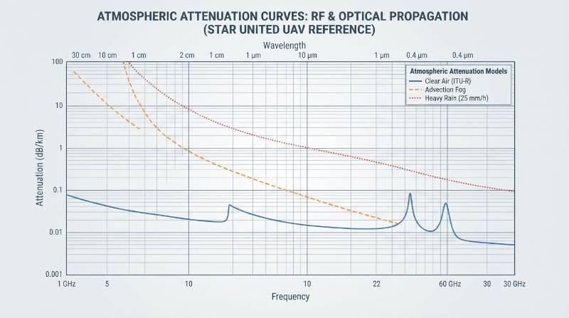
Electromagnetic Propagation and Atmospheric Degradation Dynamics
Sensor capability is governed by electromagnetic wave interaction with particulate matter in the lower troposphere. Visible (0.4–0.7 μm), Mid-Wave Infrared (MWIR, 3–5 μm), and Long-Wave Infrared (LWIR, 8–14 μm) payloads depend on ambient or radiated photon reception, governed by the Beer-Lambert extinction equation: I = I0 · exp(-γ · R) Where I is received intensity, I0 is initial source intensity, γ is the total atmospheric extinction coefficient (γ = αabsorption + βscattering), and R is slant range. In advection fog (droplet diameter 10–20 μm) or low cloud cover, Mie scattering causes γ to exceed 30 dB/km, rendering optical and thermal sensors blind at ranges beyond 200–300 m.Microwave Transmissivity and Rain Derating Curves
Synthetic Aperture Radar operates in the microwave regime, typically utilizing X-band (8.0–12.0 GHz, λ ≈ 3.1 cm) or Ku-band (12.0–18.0 GHz, λ ≈ 1.8 cm). Because the wavelength is orders of magnitude larger than water droplets and fog aerosols, Rayleigh scattering dominates, resulting in attenuation below 0.1 dB/km under dense advection fog. Under precipitation, attenuation increases following ITU-R P.838-3 modeling: γrain = k · (dM/dt)α Where dM/dt is rain rate in mm/hr, and k and α are frequency-dependent coefficients. For an X-band radar operating at 9.6 GHz with horizontal polarization, k ≈ 0.008 and α ≈ 1.30. At a torrential rainfall rate of 25 mm/hr, X-band signal degradation is restricted to approximately 0.52 dB/km, maintaining ground mapping functionality over a 15 km slant range where EO/IR sensor visibility drops to zero.Platform Dynamics, Motion Compensation, and Avionics Bus Integration
The mechanical and mathematical processing required to stabilize payload data differs completely between optical turrets and radar arrays. Electro-Optical and Infrared systems use closed-loop inertial stabilization within a multi-axis gimbal. Brushless direct-drive motors receive high-frequency correction updates (typically 1,000–2,000 Hz) from an internal MEMS IMU mounted directly to the optical bench, isolating airframe vibration down to <15 μrad. Conversely, a SAR sensor mounts rigidly to the UAV airframe or onto a fixed-depress bracket, using the physical forward velocity of the aircraft (v) across time (Δt) to synthesize a virtual aperture: Lsa = (λ · R0) / δcr Where R0 is the slant range to the target and δcr is the target cross-range resolution. Any uncompensated platform deviation from an ideal straight line during aperture synthesis introduces quadratic and cubic phase errors into the radar backprojection algorithm, resulting in image defocusing and azimuth smearing.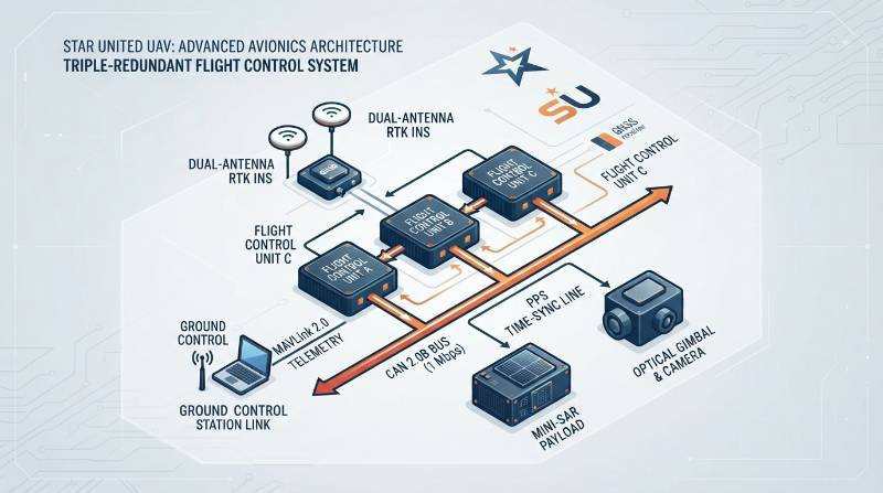
Real-Time Motion Compensation and Avionics Protocols
To avoid phase errors exceeding π/4 radians, SAR arrays mandate sub-centimeter-precision trajectory tracking. Platforms must incorporate dual-antenna Real-Time Kinematic GNSS tightly coupled with a tactical-grade Inertial Navigation System (RTK/INS), outputting position, velocity, and attitude (PVA) states at ≥200 Hz with latency <2 ms. Modern implementations utilize dual-channel CAN 2.0B buses operating at 1 Mbps alongside hardware-level Pulse-Per-Second (PPS) triggers to synchronize raw radar chirps with carrier phase measurements. Systems executing these operations rely on redundant flight control systems to govern trajectory coherence while streaming target telemetry via MAVLink 2.0 to ground control stations.SWaP-C and Flight Endurance Derating Across Host Airframes
Size, Weight, Power, and Cost (SWaP-C) dictate payload viability. A typical stabilized multi-sensor EO/IR gimbal (e.g., 30× visible zoom + 640×512 uncooled LWIR + laser rangefinder) imposes a structural mass of 1.2 to 3.5 kg and draws 15 to 45 W. A tactical mini-SAR with integrated Ground Moving Target Indication (GMTI) weighs 3.8 to 8.5 kg, requiring 120 to 220 W of continuous electrical power to drive the traveling wave tube or solid-state gallium nitride (GaN) power amplifiers.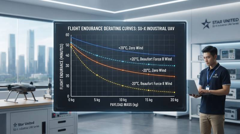
Mass and Temperature Derating Profile
On enterprise multi-rotor systems, every additional kilogram of payload mass shifts the motor operating point along the non-linear thrust-to-power curve, reducing propulsion efficiency (measured in g/W). Consider an industrial benchmark flight profile executed on heavy-lift rotary UAV platforms running a 12S/14S lithium-ion battery architecture:- Unladen Profile (0 kg payload): 72 minutes hover endurance at ISA sea level (20°C, 0 m/s wind).
- Nominal Operational Profile (15 kg payload): 42 minutes hover endurance under 12 m/s continuous airflow.
- Extreme Environmental Boundary (-20°C, 18 m/s wind): Endurance derates to 31 minutes. Increased battery internal impedance reduces nominal pack capacity by 28%, while continuous aerodynamic stabilization increases average current draw by 35%.
Benchmark Case: Maritime EEZ Patrol in Beaufort Scale 8 Gust Environments
To quantify payload trade-offs under real-world limits, field evaluations were conducted off coastal infrastructure using the Star United UAV heavy-lift platform configured for dual-payload persistent patrol. The operational scenario required persistent surveillance across an offshore energy cluster under Beaufort Scale 8 sustained winds (17.2–20.7 m/s), dense maritime advection fog (<100 m horizontal visibility), and active marine salt spray.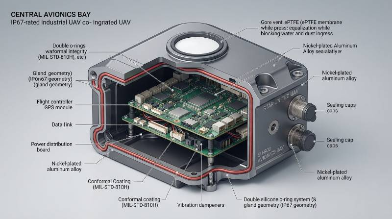
Reference Architectural Configuration
The platform integrated an X-band (9.6 GHz) mini-SAR transceiver with a co-boresighted, gyro-stabilized cooled Mid-Wave Infrared (MWIR 3–5 μm) turret across an isolated, dual-bay carbon-fiber payload interface. Mechanical and electrical isolation met strict testing boundaries:- Dynamic Sensor Power-Bus Arbitration: The avionics flight controller dynamically modulated the radar transmission duty cycle via CAN bus commands. During peak aerodynamic station-keeping maneuvers requiring >85% motor throttle, the radar transitioned to passive listening mode, protecting propulsion voltage stability.
- Coupled Motion-Compensation INS Interface: An airframe-integrated tactical RTK/INS supplied position and attitude correction over CAN 2.0B at 1 Mbps with <2 ms packet latency, mitigating high-frequency motor vibration harmonics (>120 Hz) verified per RTCA DO-160G Section 8 (Category S).
- Marine Salt-Spray Protection: All chassis interfaces, quick-disconnect motor arm latches, and internal payload bays maintained industrial inspection UAS reliability, validated to IEC 60529 IP67 and MIL-STD-810H Method 509.7 (salt fog endurance). Parylene-C conformal coatings protected avionics against marine electrolytic corrosion.
Lifecycle Reliability, Environmental Testing, and TCO Analysis
Enterprise procurement decisions must factor Total Cost of Ownership (TCO) beyond initial capital expenditure. Optical, thermal, and microwave sensors possess distinct mechanical failure points, service life ceilings, and maintenance intervals.Subsystem MTBF and Overhaul Cycles
- Cooled MWIR Turrets: Rely on closed-cycle Stirling mechanical cryo-coolers to depress the focal plane array to 77 Kelvin (-196°C). These cryo-coolers have a verified operational MTBF of 8,000 to 10,000 hours, requiring depot-level maintenance and seal rebuilds every 2,000 to 2,500 flight hours.
- Solid-State Mini-SAR Payloads: Feature no moving internal elements, yielding an MTBF exceeding 15,000 hours. Failure modes are concentrated in the RF front-end power amplifier due to thermal cycling and impedance mismatch from antenna damage.
- Gimbal Mechanical Bearings & Slip Rings: 3-axis EO/IR gimbals require slip-ring replacement and optical recalibration every 1,000 hours to mitigate angular jitter creeping above 25 μrad.
- Propulsion Bearing Cycles: High-stress operations in humid or saline air mandate motor bearing replacement cycles every 500 flight hours to prevent high-frequency mechanical vibration from desynchronizing SAR phase centers.
Compliance Standards Framework
Airframe and payload integrations must satisfy standardized structural, electrical, and operational protocols:- ASTM F3298-19: Standard Specification for Design and Construction of Large Unmanned Aircraft Systems.
- ASTM F3322-18: Standard Specification for Small Unmanned Aircraft System Parachutes and Flight Safety.
- ISO 21384-3: Unmanned aircraft systems — Part 3: Operational procedures.
- IEC 60529 IP67: Ingress testing confirming complete dust exclusion and water submersion resistance up to 1.0 m depth for 30 minutes.
Frequently Asked Questions Regarding Airborne EO/IR and SAR Selection
In Long-Range Industrial Surveillance, Should Platforms Deploy Mini-SAR or EO/IR Payloads?
Sensor selection is dictated by the operational atmospheric extinction coefficient and target identification criteria per STANAG 4347. If the operational theatre encounters recurring advection fog, cloud cover, smoke, or marine moisture layers where optical extinction γ exceeds 10 dB/km, mini-SAR operating in the X or Ku band is mandatory to achieve all-weather wide-area mapping. However, SAR systems cannot resolve visual colors, read vessel hull identification markings, or provide direct radiometric surface temperatures. The standard deployment architecture is a cross-cued configuration: a high-efficiency synthetic aperture radar running real-time GMTI scans wide areas through cloud cover to isolate targets, dynamically vectoring a co-boresighted EO/IR gimbal turret to execute optical Detection, Recognition, and Identification (DRI) once the airframe closes the line of sight.How Can an Enterprise Procurement Auditor Verify Genuine IP67 Ratings and Beaufort Scale 8 Wind Resistance on a UAV Platform?
Procurement auditors should reject vendor-supplied self-declarations and demand accredited third-party test documentation. For ingress verification under IEC 60529 IP67, mandate lab reports from an ISO/IEC 17025 accredited facility verifying Category 1 dust-chamber negative pressure drawdown (8 hours continuous) followed immediately by 1.0 m water submersion for 30 minutes, supported by post-test teardown inspections confirming zero moisture inside motor ESCs, battery bays, or avionics enclosures. To substantiate Beaufort Scale 8 continuous wind resistance (17.2–20.7 m/s, gusts to 22 m/s), auditors must review raw telemetry logs (.bin or .ulog formats) extracted from calibrated open-jet wind tunnel tests or sea-trial flight records. The propulsion system must demonstrate a minimum 25% motor thrust margin (pulse-width modulation duty cycle <80%) during steady-state station-keeping in 18 m/s airflow, with flight attitude roll/pitch standard deviations constrained to within ±1.2°.Procurement Integration Protocol: 3-Step System Qualification Pathway
Integrating complex payloads onto enterprise-grade UAV airframes demands a rigorous engineering qualification workflow to eliminate mechanical, electrical, and thermal failures before hardware deployment.- Operational Parameter & Mission Envelope Ingestion: Define payload SWaP parameters (mass, dimensions, continuous/surge wattage), operational ceilings (density altitude AMSL), thermal limits (-20°C to +50°C), and required wind penetration thresholds (sustained vs gust limits).
- System Architecture & Derating Modeling: Receive verified platform interface control documents (ICDs), mechanical CAD models (STEP format), electrical bus arbitration schemas, and high-fidelity flight endurance derating curves matched to your payload profile within 24 hours.
- Engineering-Led Consultation & Flight Demonstration: Review Hardware-in-the-Loop (HIL) telemetry logs, inspect third-party RTCA DO-160G and IEC 60529 test certificates, and participate in a live flight demonstration evaluating attitude stability and sensor interface performance.
Request Avionics Integration Schematics & Mission Modeling
Consult directly with our Principal UAV Systems and Avionics Integration Engineers. Request detailed platform CAD STEP files, bus communication ICDs, and custom payload endurance derating models for your surveillance deployment.
Contact Systems Engineering Team